Flow Meters: What are they, how they work, and what they are used for
In a Nutshell
These flowmeter automotive parts can be considered the engine’s “nose”. Think of your car’s engine as a living thing that needs to breathe. The amount of air it takes in, determines how hard it is working.
For the engine to run efficiently, the engine’s computer or “ECM“, for “Engine Control Module“, needs to know exactly how much air is entering the engine, to inject the proper fuel amount accordingly. This is where the Air Flow Sensors come in. It measures the incoming air and reports back to the ECM.
More Details
The ECM needs the information from the flowmeter to do the fuel calculation because the more air that comes in, the more fuel that needs to be injected to keep a balance for best efficiency and power.
This sensor is always located in the engine’s air intake stream, between the air filter (air cleaner) and the throttle body (place where the carburetor used to be).
Three (3) types of air flow sensors
I. Mass Air Flow (MAF) Sensor Type
This is the “Hot Wire” type. This is the most common type of air flow sensor found in modern cars. This is the most efficient of the three types because it measures airflow by mass, and NOT by volume, as the other types do.
Why? Because of the oxygen content. The density of the same volume of air changes with temperature. The higher the temperature, the less dense the air, hence, the less amount of oxygen per volume. On the other hand, colder air contains more oxygen by volume because of a higher density. Haven’t you noticed how well your car performs at night or on cold days? This is why.
How it works
This type of flowmeter has three main parts inside its plastic housing:
1. A thermistor: A device that measures the temperature of the incoming air by varying its internal resistance related to temperature.
2. A platinum hot wire: A very thin wire that is heated up.
3. An electronic control circuit: The “brain” of the sensor that manages the wire’s temperature and creates the output signal to the ECM. This circuit is contained within the sensor’s housing itself.
Imagine you’re trying to keep a piece of toast at a constant temperature, but someone keeps blowing on it. The harder they blow, the more you have to turn up the toaster to keep it warm. This sensor works the same way.
So, in the car system, the “toast” and the “toaster” analogy works like this:
1. The electronic circuit heats the platinum wire to a specific temperature, which is always set to an amount above the incoming air temperature measured by the thermistor.
2. When more air flows into the engine (because you step on the gas), it hits the hot wire and cools it down.
3. The electronic circuit instantly senses this cooling and sends more electrical current through the wire to heat it back up to its target temperature.
4. The circuit measures this change in current. The more air flowing, the more current needed.
5. It then converts this current measurement into a voltage signal that is sent to the ECM and is “interpreted” as the incoming air value.
This type of sensor often has the Intake Air Temperature (IAT) sensor built right into it too.

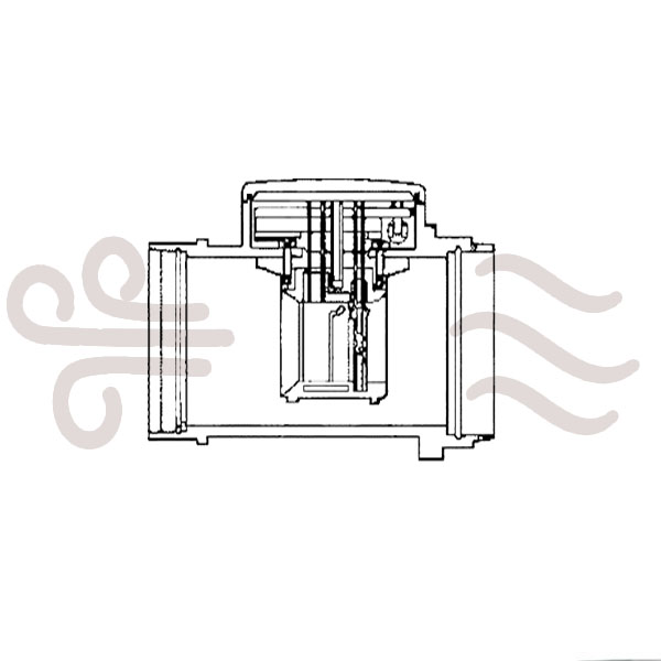
II. Vane Air Flow Meter: The Old-School “Flapper Door”
This is an older style of air flow sensor and is much more mechanical than the hot wire type. You can often identify it by its boxy shape.
This sensor is built like a small wind tunnel with internal moving parts. It consists of:
1. A measuring plate: A “flapper door” that swings open as air flows in. The more the air, the larger the opening angle.
2. A return spring: Pushes against the flapper door to close it.
3. A potentiometer: A variable resistor connected to the flapper door. Think of it like a volume knob on an old radio.
4. A compensation plate: Acts as a shock absorber to keep the measuring plate steady.
5. A bypass passage and idle adjusting screw: For fine-tuning the air mixture (factory set and not meant to be adjusted).
6. A fuel pump switch: A safety feature that turns on the fuel pump only when air is flowing (engine is running).
7. An Intake Air Temperature (IAT) sensor: Senses the temperature of the incoming air to try to adjust the output data value according to temperature (colder = denser).
How it Works:
This is a simple, physical cause-and-effect system.
1. When you step on the gas, the engine sucks in air. The force of this air pushes against the measuring plate, opening it like a door at certian angle.
2. The harder the engine sucks air (more air volume), the further the door opens against the spring (wider angle).
3. This measuring plate is connected by a shaft to the “volume knob” (potentiometer). As the door opens, it “turns the knob,” changing the electrical resistance, hence, varying the current that results from the fixed applied voltage.
4. The resulting voltage changes are fed into the ECM. The position of the door directly translates to an air volume reading.

III. Karman Vortex Air Flow Meter: The “Whirlwind” Sensor
This type of sensor uses clever physics to measure air without any moving parts that wear out (like the flapper door) and offers the minimum constriction to the air path.
This type of sensor looks like a simple tube but contains some sophisticated parts:
1. A vortex generator: A small, triangular-shaped bar in the middle of the air stream.
2. A mirror made of thin metal foil.
3. A photo coupler: This is a combination of an LED (Light Emitting Diode, like a “lamp”) and a photo transistor (light sensor).
How it Works:
This sensor relies on a natural phenomenon called a “Karman vortex street“. It is as follows:
1. As air flows past the triangular vortex generator, it creates a pattern of swirling vortices behind it. Think of the swirling, fluttery wake that trails behind a fast boat on the water.
2. The frequency of these vortices is directly proportional to the speed (and therefore volume) of the air. Think of this frequency as how fast the swirls are created. So, more air = faster swirls.
3. These air swirls are channeled towards the thin metal foil mirror, causing it to vibrate or oscillate at the same frequency.
4. The photo coupler (LED) shines a light on this mirror. As the mirror vibrates, it either reflects the light onto the photo transistor or deflects it away. This acts like a high-speed, flashing light switch.
5. The photo transistor turns on and off at the same frequency as the mirror’s vibration, creating a digital signal.
The Karman Vortex sensor produces a digital square wave signal. Imagine a light flickering on and off very quickly. As engine RPM increases, the frequency of this square wave signal will increase. The signal doesn’t change in strength (voltage), but in how fast it pulses (frequency).
Note about the Karman vortex street:
The “Kármán vortex street” phenomenon is named after Theodore von Kármán, a Hungarian-American engineer and fluid dynamicist (1881–1963). Although vortices had been observed and photographed earlier by others, von Kármán was the first to mathematically describe the stability of this alternating pattern of vortices.
And for the “street” Structure, the term “street” describes the visual pattern: two parallel, parallel-staggered rows of vortices that form a continuous “lane” or “street” behind the obstructing object.

